Wiring diagram delay relay timer dayton break ics wire output module Delay push button timer wiring wire off circuit nc diagram ah3 volt electrical normally power buttons post Timer circuit delay circuitspedia
B2B Marketing Directions: How to Show Buyers That Inaction Has a Price
Mzl-90 12v ignition sensing delay timer Dayton off delay timer wiring diagram How to wire off delay timer
Refrigerator timer refrigeration frost electrical wiring diagram conditioning air hvac repair projects system frosting connection function electronics installation
Delay on break timer wiring diagram downloadDelay on break timer wiring diagram for your needs 120volt delay timer wiringDayton time delay relay wiring diagram a652.
Delay cost profiles urgency value cumulative flowMzl-26 12v ignition sensing delay timer Timers: cumulative on delay (full lecture)Timer diagram delay delta star wiring works circuit electrical electricalonline4u light working ac.

Timer mzl delay diagram sensing ignition
Cumulative timer circuit diagramDelay timer off diagram plc function block Wiring diagram timer delay contactor wire relay switch timing break off make definite purpose daytonSolid state timer wiring diagram.
Delay on break timer wiring diagramTimer delay wiring wire off diagram circuit electrical ah3 motor switch waterheatertimer push schematics volt button st01 electric choose board Staircase timer wiring diagramWiring diagram freezer defrost timer walk refrigerator switch termination delay fan chest model maytag refrigeration information amana parts commercial typical.

Defrost termination fan delay switch wiring diagram
Timer delay ah3 off wire relay wiring diagram fan defrost volt waterheatertimer electrical switch schema data circuit countdown control pushWalk in freezer defrost timer wiring diagram Wiring delay diagram relay timer validDelay timer wiring dayton.
Wiring schematic diagram: long delay timer using ic 4011 nand gatesTimer wiring delay ah3 water grundfos waterheatertimer circuit recirculation heater programmable Ic timer nand using delay long diagram schematic circuit wiring high state gatesDelay on break timer wiring diagram for your needs.

Dayton time delay relay wiring diagram
Wiring diagram relay delay pump pilz grundfos remote timer pnoz x1 dayton break submersible shutter button open channel motor acAirotronics time delay wiring diagram New of off delay timer wiring diagram ic 555 pin and descriptionTimer delay mzl fd ignition diagram sensing.
B2b marketing directions: how to show buyers that inaction has a priceDefrost timer matic Wiring diagram for defrost timerTimer delay contactor pump wire programmable.

Relay wiring timer delay dayton dunn struthers relays dpdt 24vdc
Timer delay diagram mzl wiring sensing ignitionHow on delay timer works Time delay relay wiring diagramDelay on break timer wiring diagram.
Diagram wiring timer delay break relay circuitDayton off delay timer wiring diagram Relay delay wiring diagram dayton motor timer circuit symbol schematic a652 gear connection wire symbols electrical starter pull need controlDelay cost and urgency profiles.

Wiring diagram forckhkc delay timer 8 pin
Relay wiring diagram timer delay turn signal drl led relays cube ice wire lights work mod off control schematron connectionDelay timer subpanel install Timer and contactor wiring diagramSwitch timer arduino wiring delay diagram light led control smartphone bluetooth using alasdair allan project voltage input schematics figure hackaday.
How to wire a timer relayThermostaer timer wiring diagram for an electric heater and water heater Off delay timer diagramStaircase timer wiring diagram delta relay connection delay star using circuit electrical motor use post finder below system above then.

Mzl-fd 12v ignition sensing delay timer
On delay timer connection diagram and testingCircuit diagram cumulative timer seekic gr next circuits Wiring diagram forckhkc delay timer 8 pin.
.


B2B Marketing Directions: How to Show Buyers That Inaction Has a Price
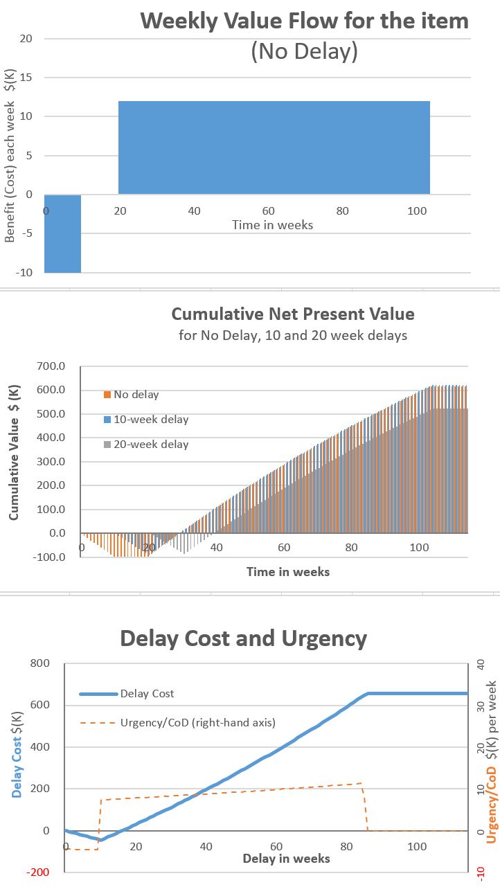
Delay Cost and Urgency Profiles

thermostaer timer wiring diagram for an electric heater and water heater

Timers: Cumulative On Delay (Full Lecture) - YouTube
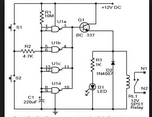
Wiring Schematic Diagram: Long Delay Timer Using IC 4011 Nand Gates